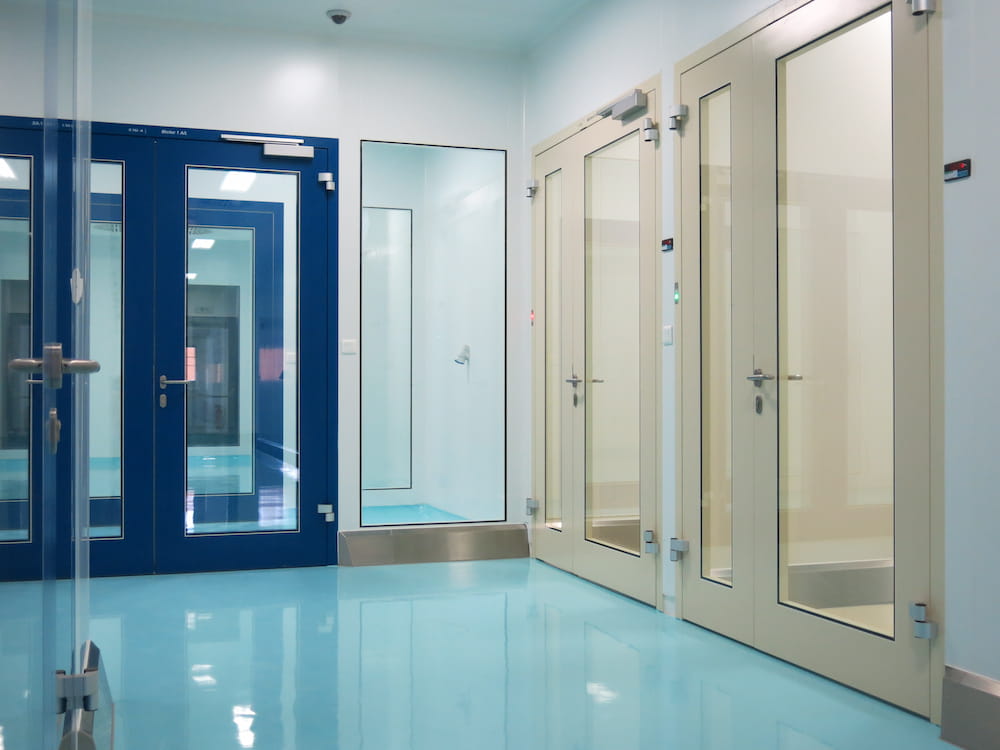
Gate Control Unit for mutual door interlocking
GCU – A powerful solution.
With our gate control units, up to 12 doors and interlocks can be controlled and monitored together. The gate control unit is modular and has a master module to which further slave modules can be connected. Three doors per module can be integrated into the control system. This means that additional doors can also be connected to the control system at a later date.
Thanks to our many years of experience with various interlock control concepts, we have been able to combine the advantages of different control concepts in our new Gate Control Units (GCU). This gives you a high degree of flexibility even for extensive room projects. Modern control concepts for clean room and airlock doors reliably prevent cross-contamination from different room areas and are thus an indispensable component for a fault-free cleanroom system.


- Conforms to the regulations from the EltVtR, as well as the generally recognised rules of technology.
- The interlock control system is pre-configured ex works.
- The interlock control system can be used for several interlocks simultaneously.
- The recovery/purge time can be set individually for each door.
- Modular design: The control system can be extended by 3 additional interlock doors per module.
- Screwless traffic light display (can be replaced if necessary).
- Optionally, a discretion circuit can be realised with the GCU.
- Optical status display via RGB. Up to 13 different statuses can be displayed, coloured or flashing.
- The control unit can be integrated in the cleanroom within a cleanroom-compatible control cabinet.
- Alternatively, the control can be positioned outside the cleanroom.
- All hinged doors are mechanically locked via an emergency exit door opener. In an emergency, the mechanical lock can be overridden.
- Optionally, the override actuated in an emergency can only be reset via a key switch.

Lock control GCU-Master 3
For mutual interlocking of up to three doors in an interlock matrix. The configuration is done ex works. The interlock control allows:
- Setting of the interlocking type: active/passive per interlock door
- Setting of the recovery times per door
- Door status query (e.g. for GLT)
- Alarm signalling contact (configurable)
- Configuration of 5 additional external contacts (e.g. discretion circuit, Open All, etc.)
- Colour configuration of the traffic light display (RGB)
The interlock control unit is connected to a terminal box to which peripheral devices can be connected separately. Electrical connection: 24 V DC or 230 V AC via power supply unit to Schuko socket (DE). Supply cable and connection on site.
Interlock control unit GCU Slave +3
GCU extension module for interlock control GCU Master: Allows the locking of three additional doors.
Interlock function GCU, swing doors: The interlock function for swing doors in escape & rescue routes.
Interlock function GCU, high-speed door / sliding door: Lock function for high-speed door
Sluice control, emergency stop module Master 6: Emergency stop module for interlock control
This module is required to reliably and safely switch off the interlock function. The emergency stop module can be used to de-energise up to 6 interlock doors. The number can be increased with an extension module.
Interlock control, emergency stop module, slave +6
Extension module for the "emergency stop master". With this extension module, a further 6 doors can be switched off by emergency stop.
 The airlock control system and the emergency stop module are installed in a control cabinet that can be placed anywhere, even outside the cleanroom. From there, the cables are laid for each airlock door.
The airlock control system is configured and labelled at the factory according to the agreed conditions. An initial function test is also carried out at the factory. The installation is carried out on site with a simple, confusion-proof plug system. Commissioning is carried out and recorded by the tradesman using a test device.
- Control cabinet with 24V power supply
- Cable from the interlock control to the interlock function
- Configuration ex works
- Commissioning on site by means of test device
- Test protocol & documentation
- Connection to your fire alarm control panel
- Consideration of pressure level and flushing times
- Also available in explosion-proof design on request
- Presence detector or dead-man circuit can be implemented
- Changing room function / discretion circuit can be implemented
